End rotation of a propped cantilever with a rotational spring at the roller
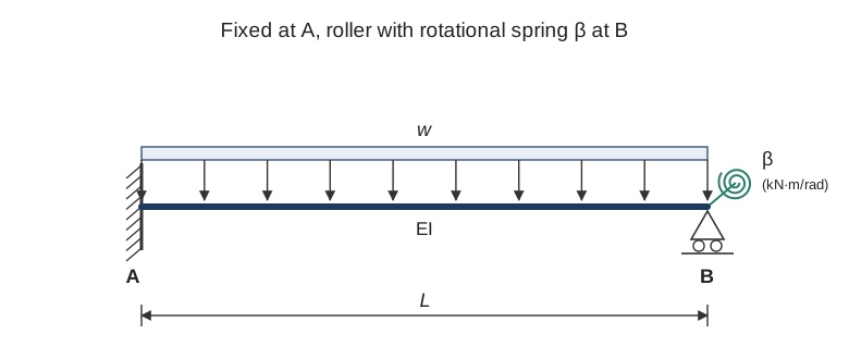
A beam is fixed at end A and supported at end B by a roller that is restrained against rotation by a rotational spring of stiffness \(\beta\). The beam carries a uniformly distributed load \(w\) over its full length \(L\). This article finds the rotation at B and shows how the spring changes it.
Idea of the solution
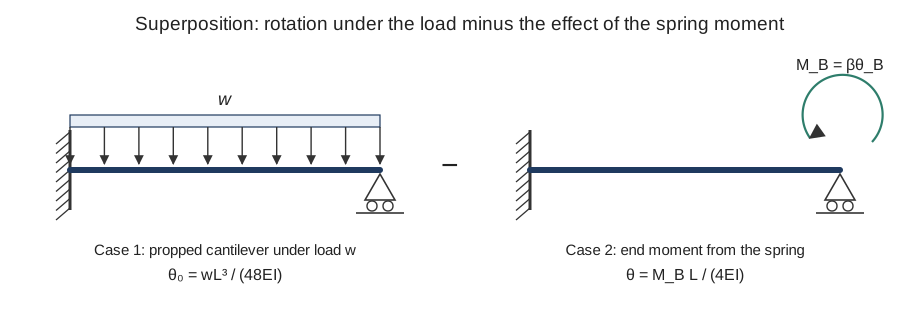
Without the spring, end B is a free roller and the beam is a propped cantilever. Its end rotation under the load is known. The spring then applies a moment \(M_B\) at B that opposes the rotation. Superposition combines the two effects:
where \(\theta_0\) is the rotation caused by the load alone and \(\theta_M\) is the rotation caused by the spring moment acting on the beam.
Step 1: rotation caused by the load
For the propped cantilever (fixed at A, roller at B, no spring) under the uniform load, with \(x\) measured from A, the bending moment is
Integrating \(EI\,\dfrac{d^2y}{dx^2} = -M(x)\) twice, and using \(\theta(0)=0\) at the fixed end, gives
At the roller, \(x = L\):
The evaluation gives \(-wL^3/(48EI)\) with the sign convention of the bending moment. The negative sign only marks the sense of rotation, so the magnitude \(wL^3/(48EI)\) is used below, with the rotation taken in the direction that the spring opposes.
Step 2: rotation caused by the spring moment
The spring moment at B is \(M_B = \beta\,\theta_B\). A moment applied at the roller end of a propped cantilever rotates that end by
so the spring moment alone rotates B by \(\beta\theta_B L/(4EI)\), in the opposite sense to the load.
Step 3: combine the two effects
Substituting into \(\theta_B = \theta_0 - \theta_M\):
Collecting the terms in \(\theta_B\):
Multiplying through by \(48EI\) gives the result:
The spring moment follows directly:
Checking the limits
| Case | Spring stiffness | End rotation \(\theta_B\) | Comment |
|---|---|---|---|
| No spring | \(\beta = 0\) | \(\dfrac{wL^3}{48EI}\) | Propped cantilever; the roller end is free to rotate |
| Intermediate | \(0 < \beta < \infty\) | between the two limits | The spring partly restrains the end |
| Rigid rotational restraint | \(\beta \to \infty\) | \(\to 0\) | The end is fully restrained against rotation |
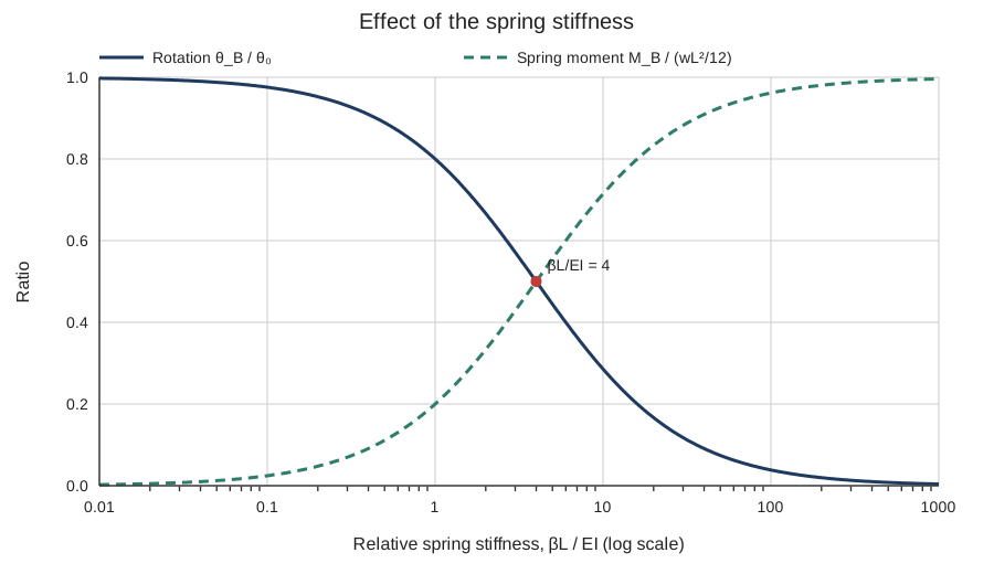
The rotation falls from the propped-cantilever value to zero as the spring becomes stiffer. This matches the physical expectation.
Worked example
Take \(w = 10\ \text{kN/m}\), \(L = 6\ \text{m}\) and \(EI = 2\times10^{4}\ \text{kN·m}^2\). Then
For a spring with \(\beta = 4EI/L = 1.333\times10^{4}\ \text{kN·m/rad}\):
The spring moment is \(M_B = \beta\theta_B = 1.333\times10^{4} \cdot 0.001125 = 15\ \text{kN·m}\). The spring halves the end rotation and carries one third of the fixed-end moment \(wL^2/8 = 45\ \text{kN·m}\) of the unsprung beam.
Assumptions
The solution assumes linear elastic material, constant \(EI\), small rotations, and a linear spring with \(M_B = \beta\theta_B\). The load is uniform and acts over the whole span. The spring stiffness \(\beta\) is in kN·m/rad and \(EI\) in kN·m², so \(\beta L/EI\) is dimensionless.